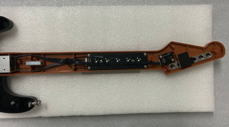
GITALLER switch shaft circuit board replacement tutorial
Difficulty: 2/5 | Estimated time: about 15-20 minutes
Shaft circuit board types
| Circuit board | Suitable for |
|---|---|
| Golden switch shaft circuit board | 3-finger players |
| Brown switch shaft circuit board | 4-finger players |
Replacement tutorial
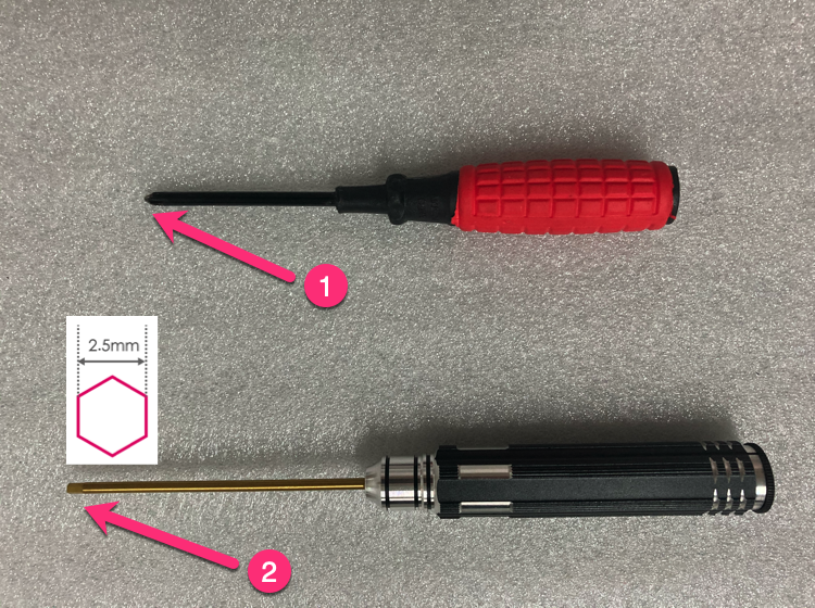
Prepare tools
Prepare Phillips screwdriver (preferably magnetic) + 2.5mm hexagon socket screwdriver.
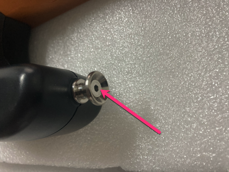
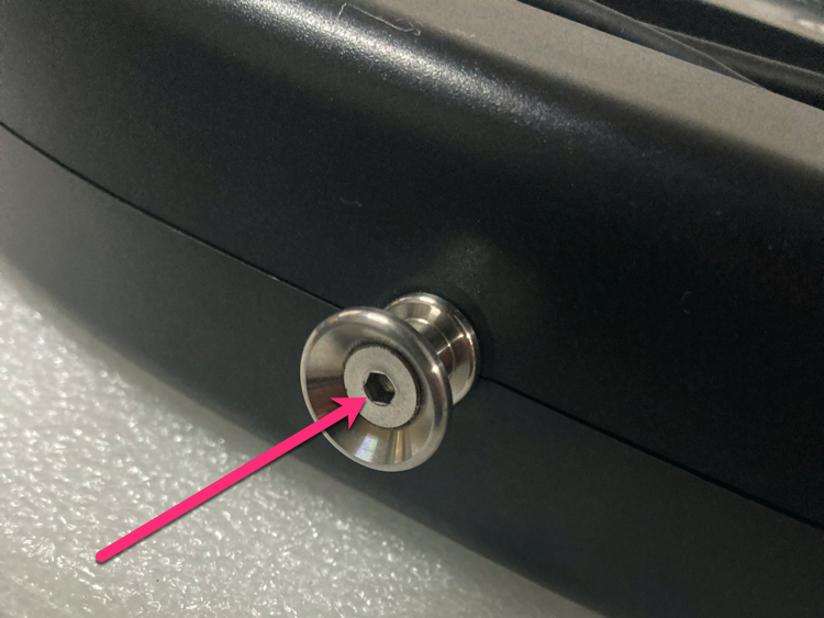
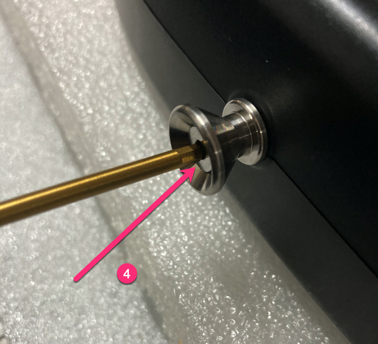
Loosen strap screws
Loosen 2 screws at the strap position with 2.5mm hex driver (just loosen, do not remove).
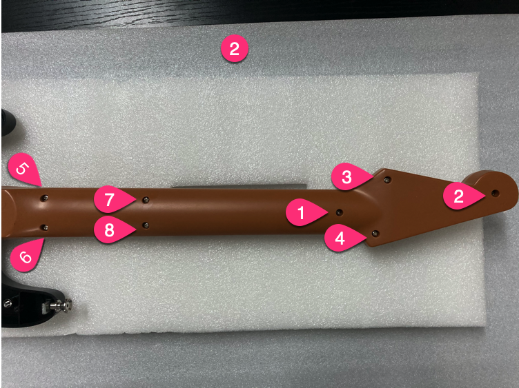
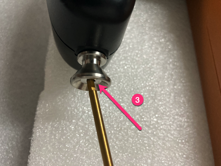
Unscrew in order
Unscrew screws in the order shown.
Unscrew 10 screws
Unscrew 10 screws.

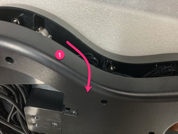
Open bottom cover
Open from the upper part, unplug the 5PIN USB cable, loosen the USB cable clip.
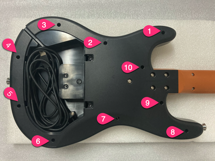
Remove screws in order
Remove screws in the order shown.
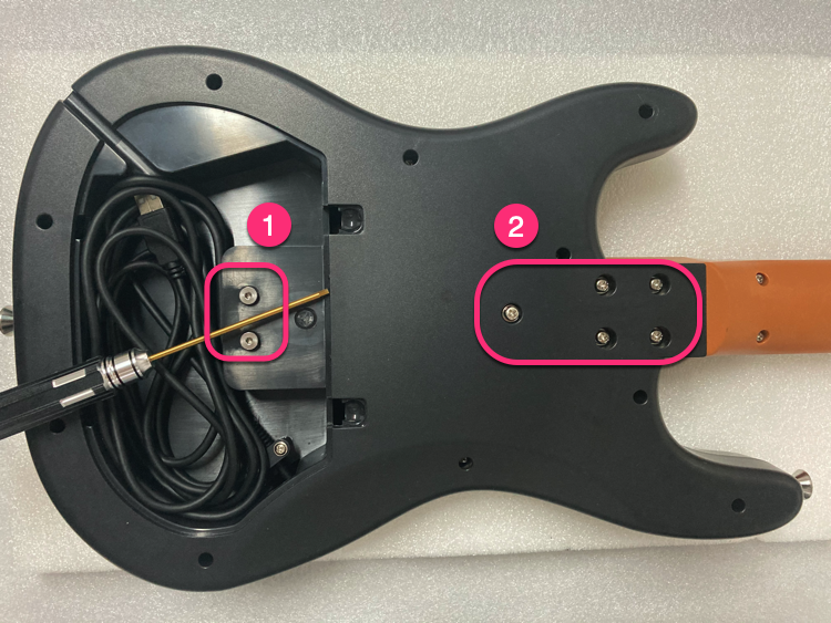
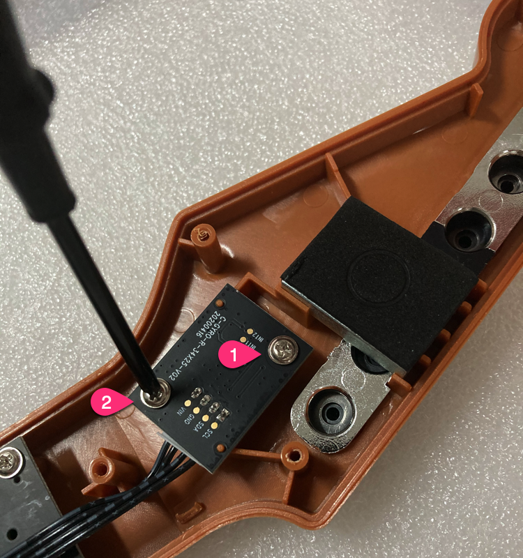
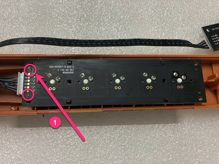
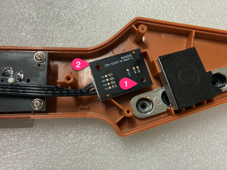
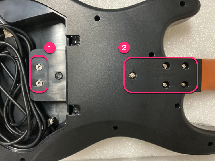
Unscrew gyro PCB
Unscrew 2 screws of the gyro PCB.
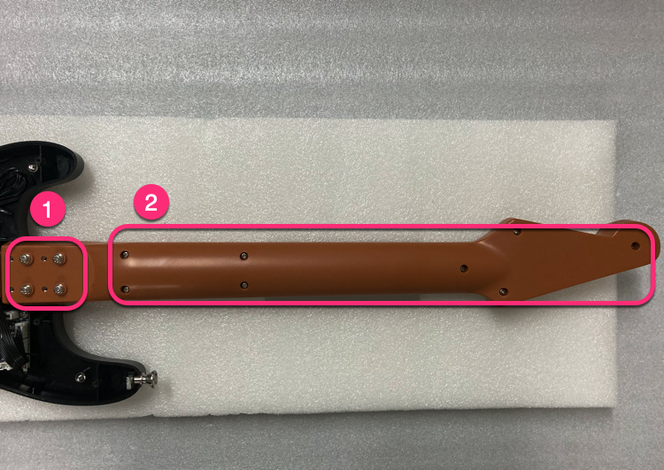
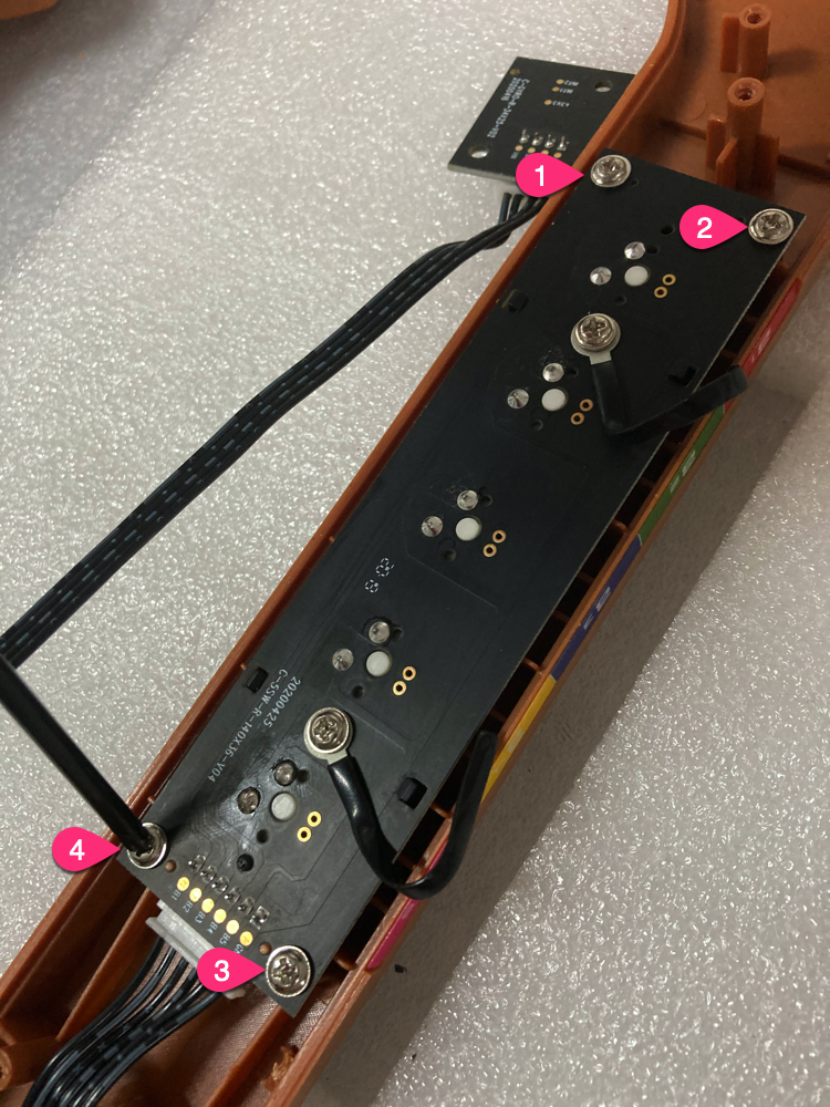
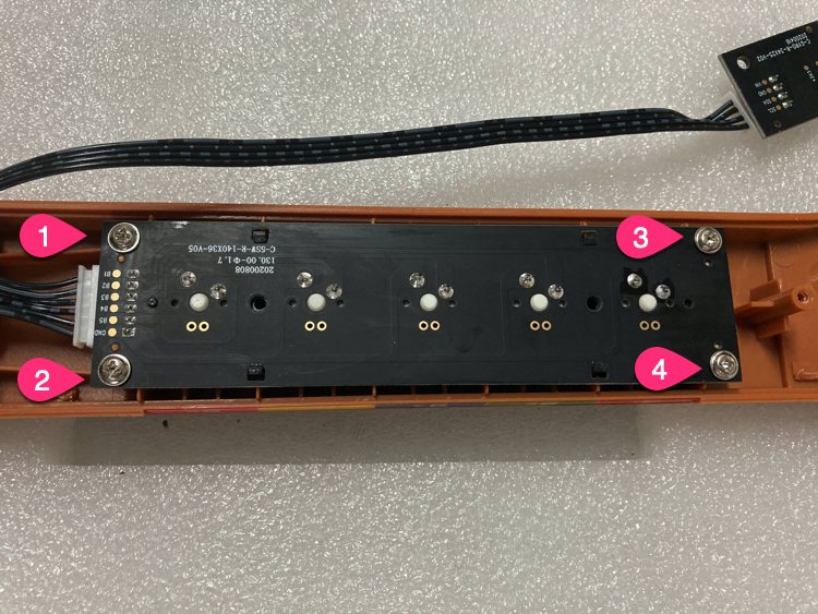
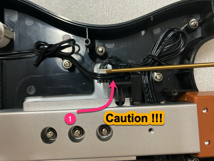
Unscrew shaft PCB
Unscrew 4 screws of the shaft PCB.
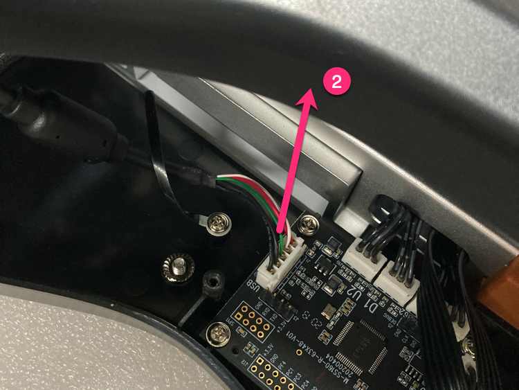
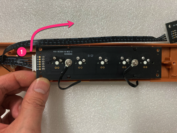
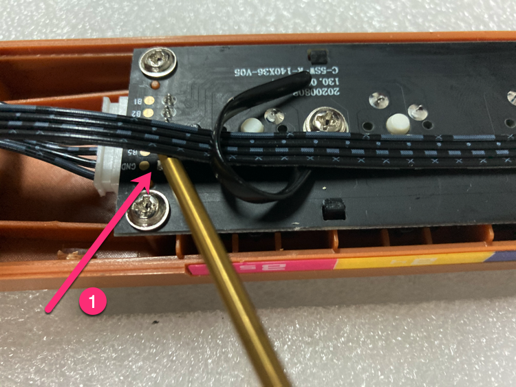
Take out shaft PCB
Take out the shaft PCB and remove the 6PIN wire (push upward).
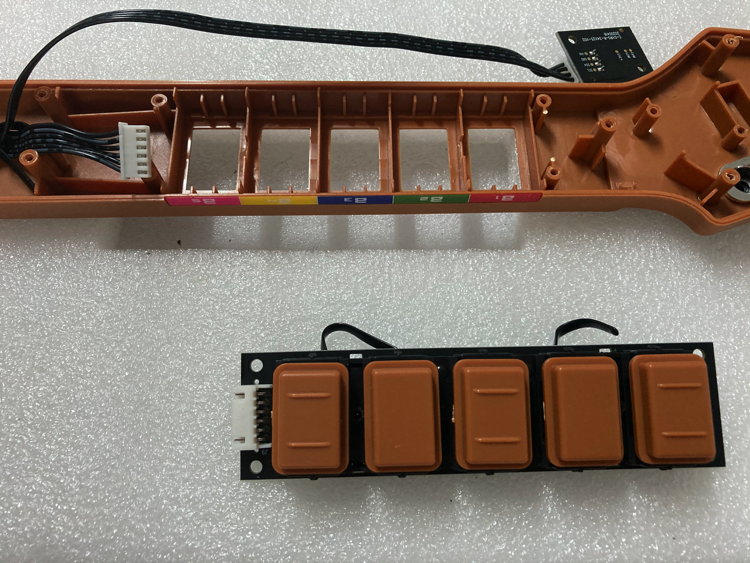
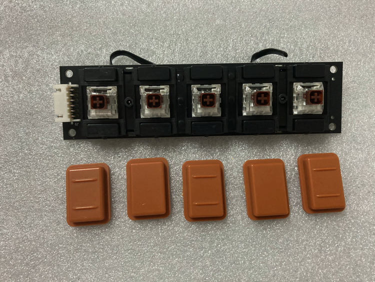
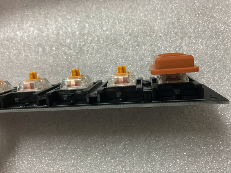
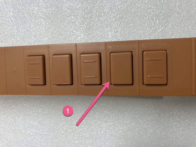
Remove keycaps
Remove all keycaps.
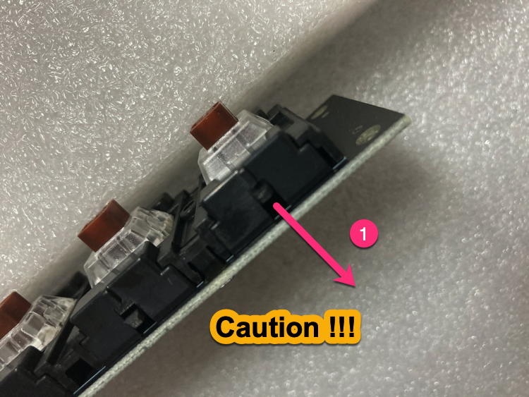
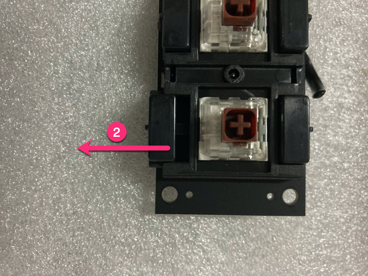
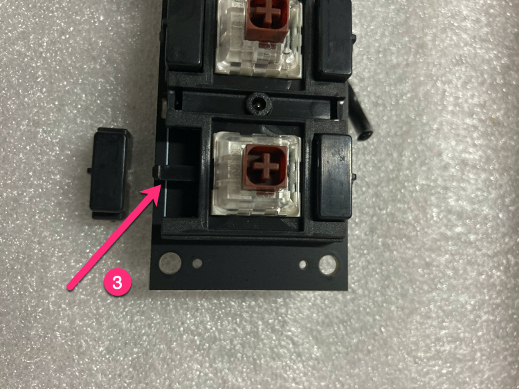
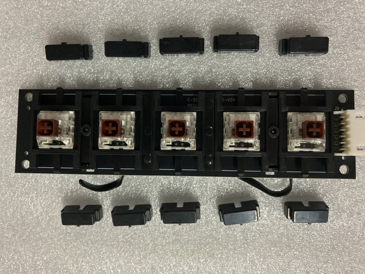
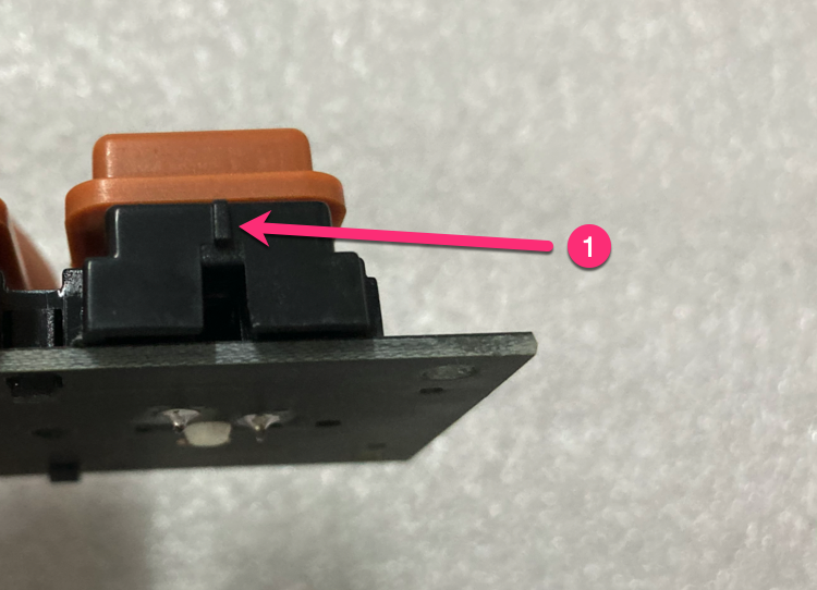
Remove limit blocks
Remove 10 limit blocks (push finger down about 1mm gently, push laterally).
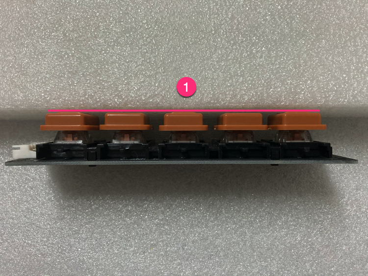
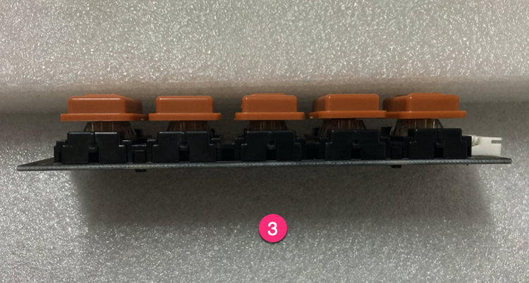
Install keycaps to new PCB
Install keycaps to the gold switch shaft PCB, check that all 5 keycaps are the same height.
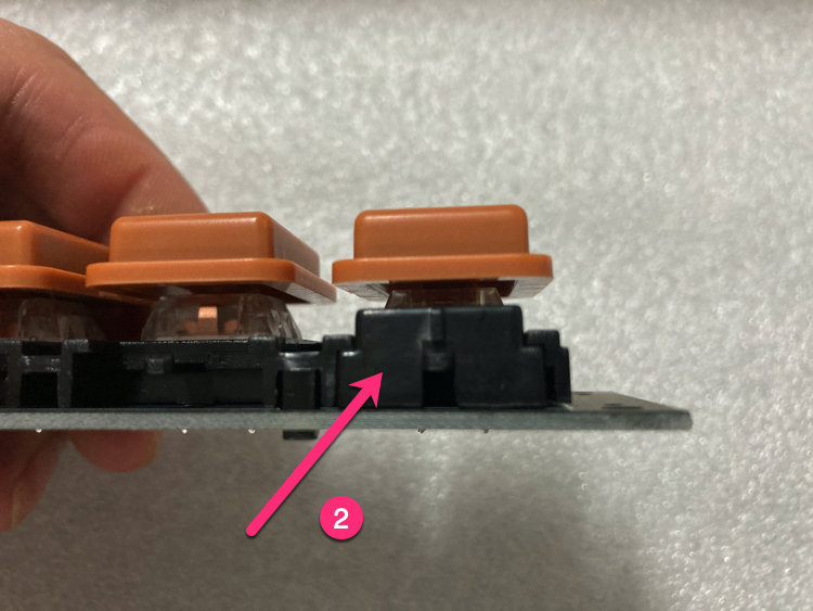
Install limit blocks
Install limit blocks (pay attention to direction).
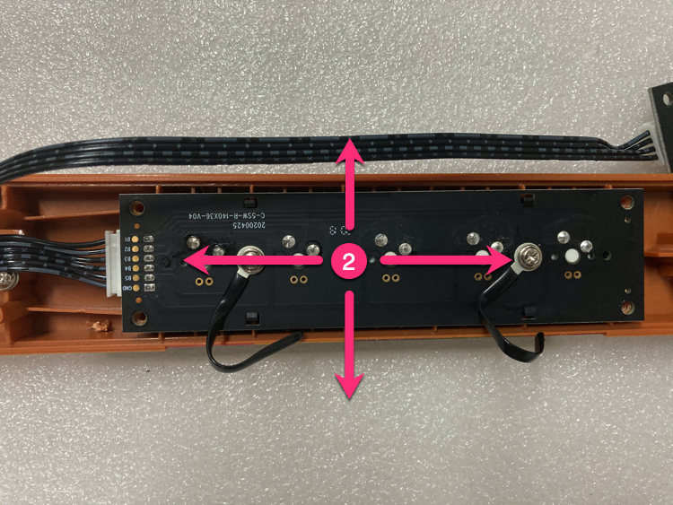
Install gold switch shaft PCB
Install the gold switch shaft PCB (leave 0.2mm gap for fine adjustment).
Install wire harness
Remove screws from the original PCB, install on new PCB.
Install gyroscope PCB
Install the gyroscope PCB.
Fix wire position
Use wire harness to fix wire position (leave gaps between wire and DIP pad).
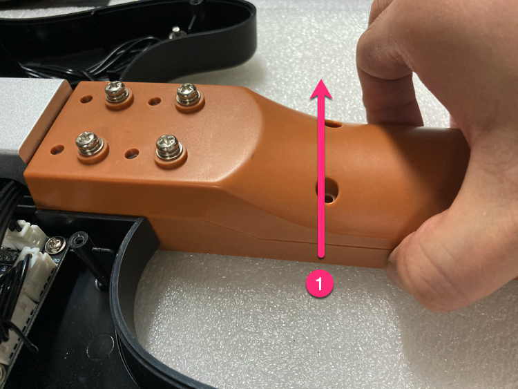
Install screws
Install screws (lift guitar neck gently to make it easier).
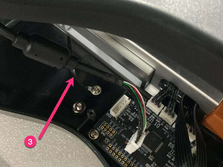
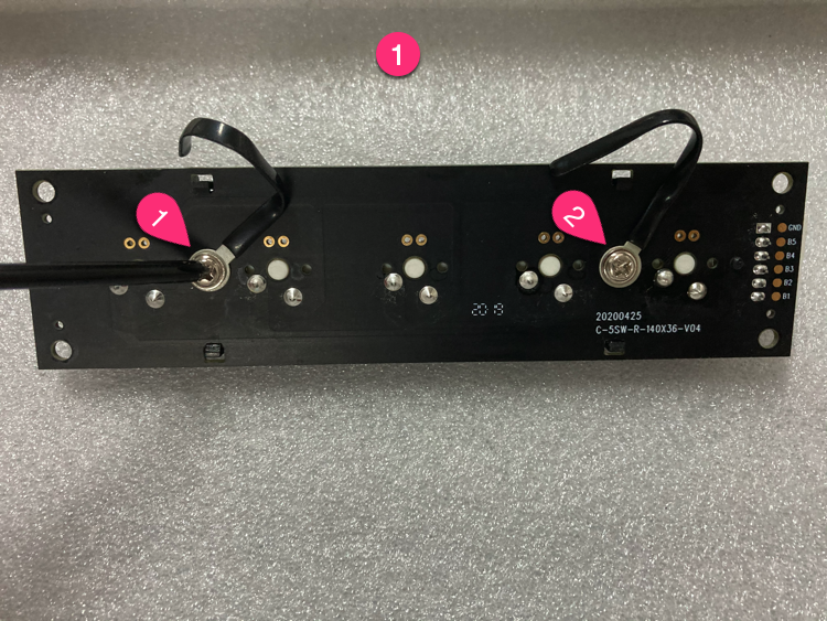
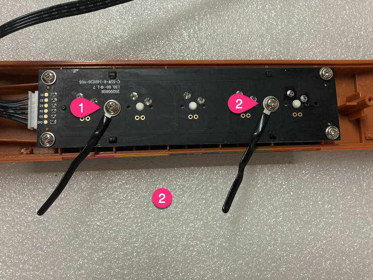
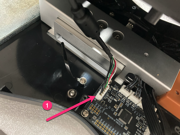
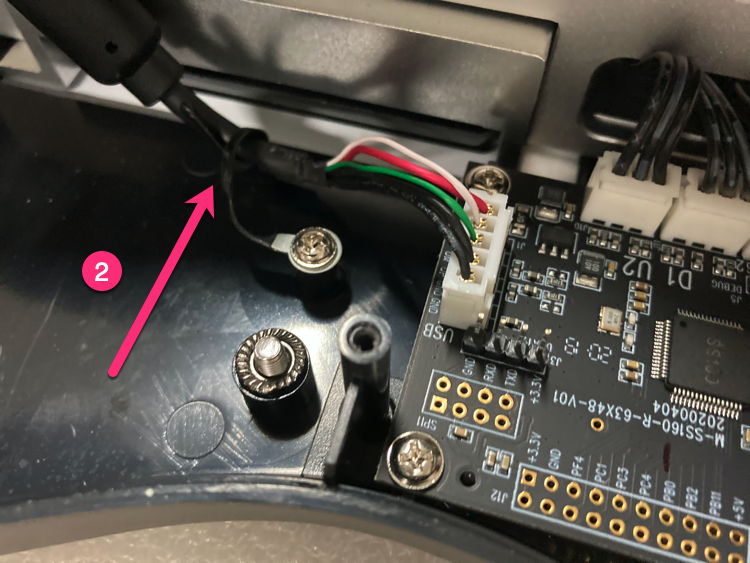
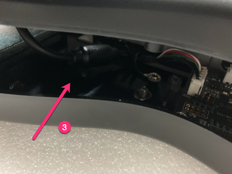
Handle button wires
Handle Select/Start button wires as shown.
Handle bottom cover
Insert 5PIN USB, arrange wire harness.
Install bottom cover screws
Bottom cover screws in order (screws 3 & 4 should not be tightened too much).
Fine-tune (if needed)
If button friction is too large: keep gaps uniform, adjust shaft PCB (0.2mm in 4 directions).
Done
Replacement complete, test all buttons to ensure they work properly.
If you cannot resolve the issue, please email us.